Results
Demonstration of Project
Below is a video showing the results of the project.
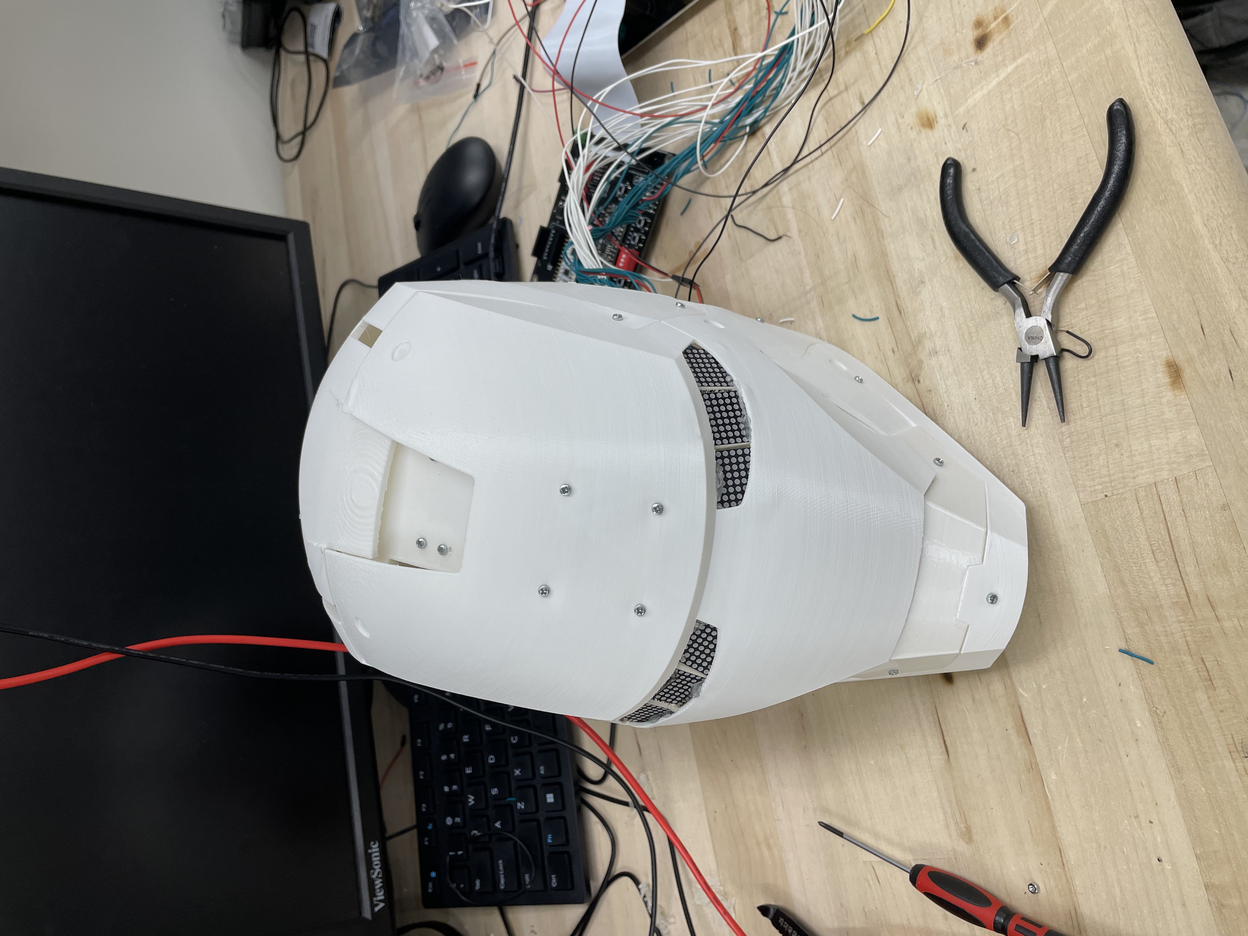
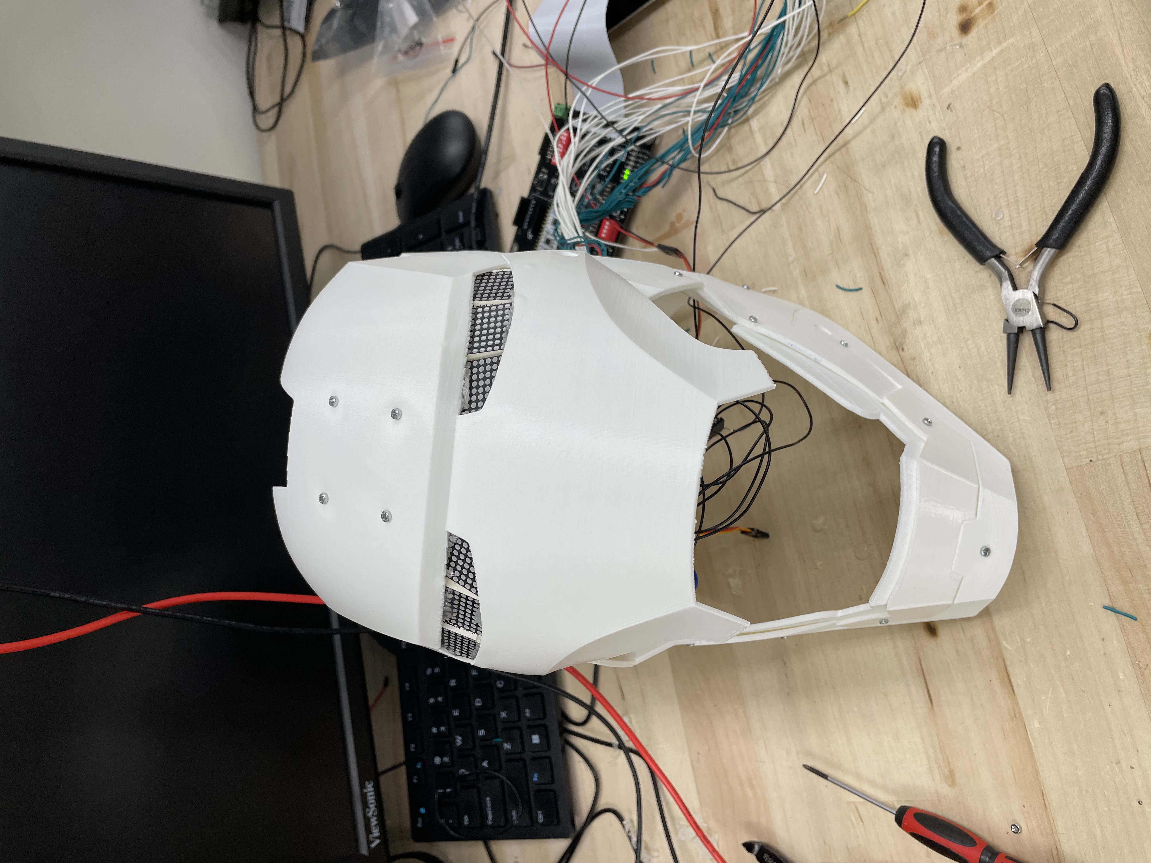
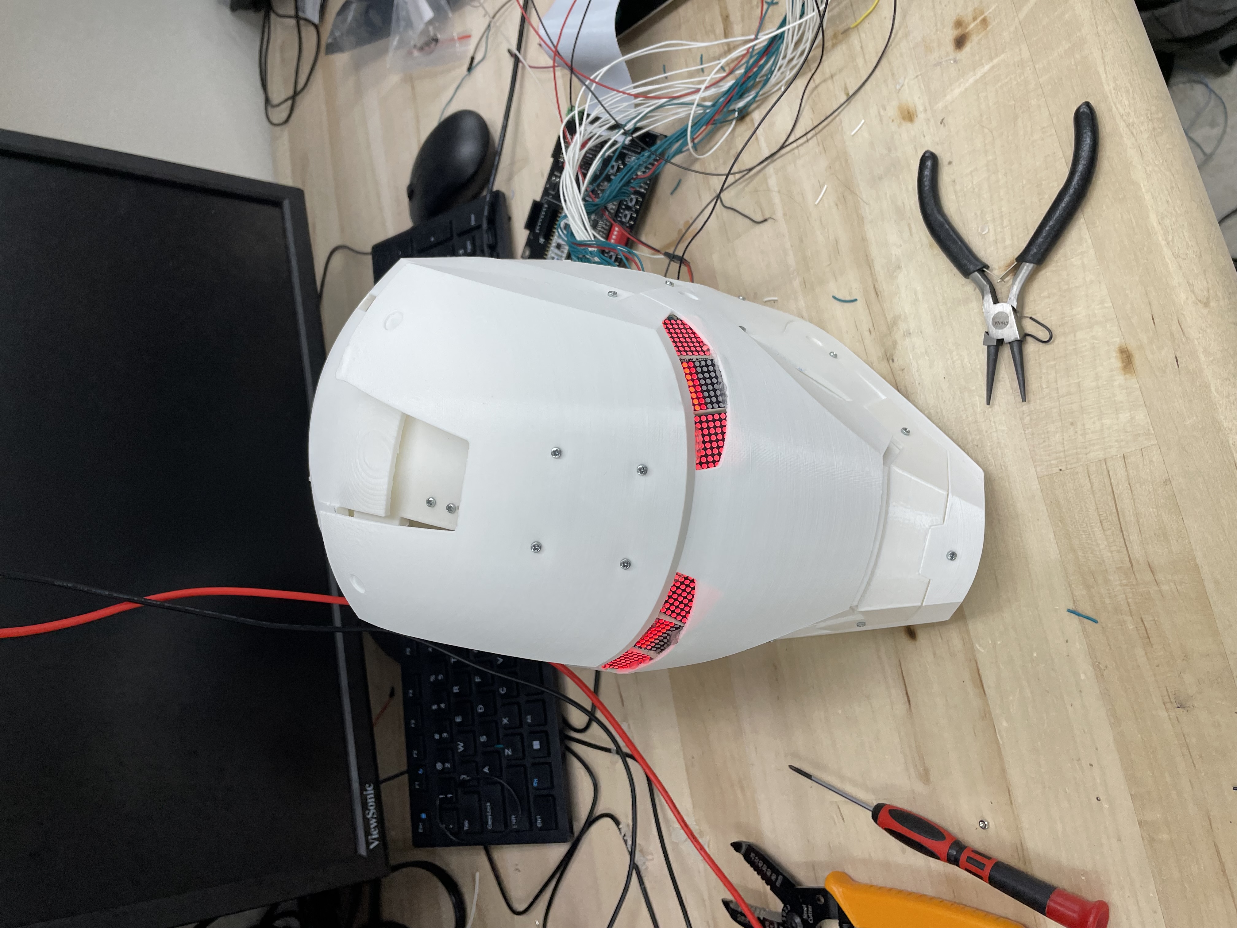
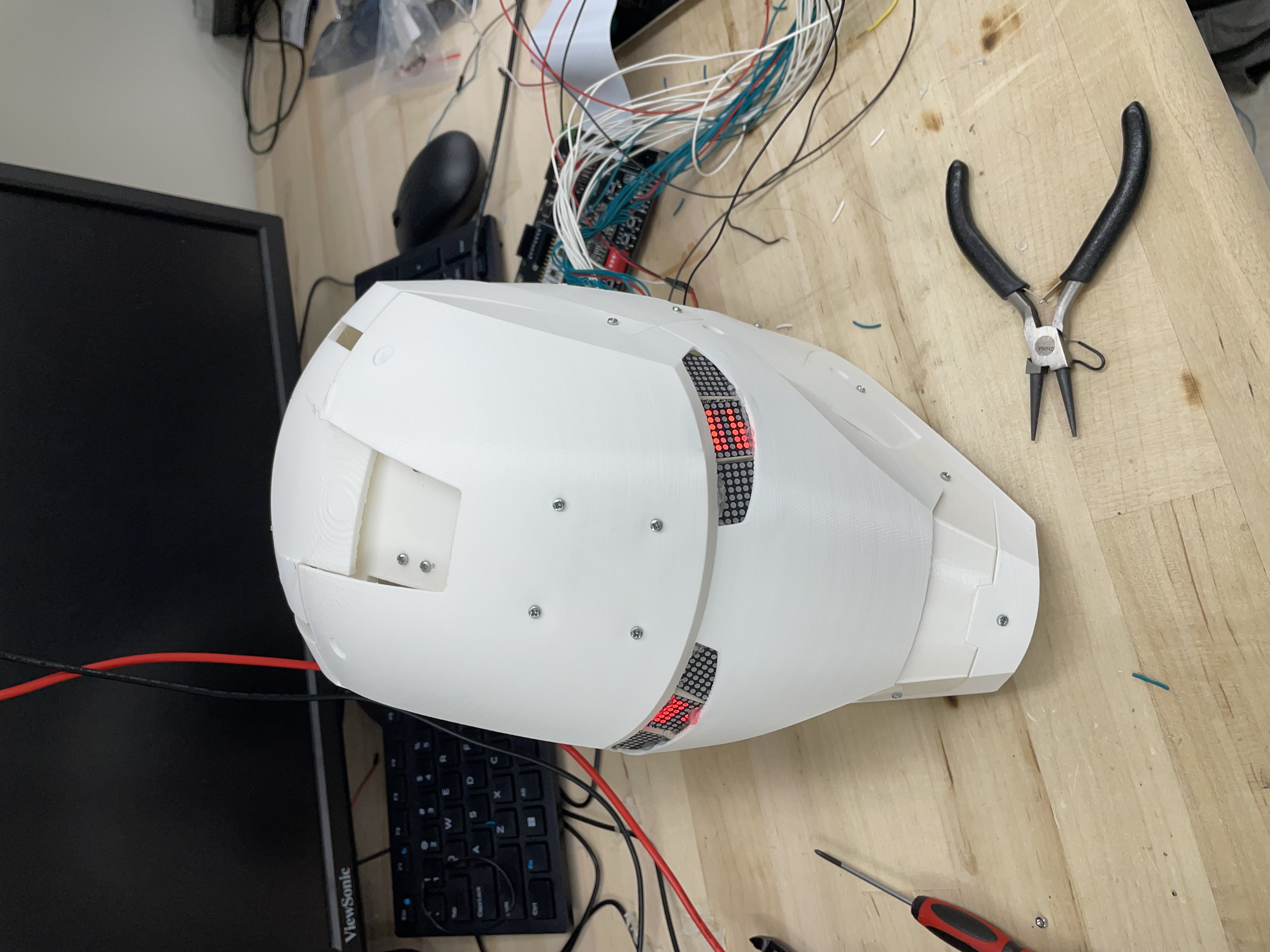
As you can see the helmet is able to open and close and the eyes light up in different patterns based on if it is open or closed, enabled or disabled. Below are various states of function of the helmet.


Results
The main goal of our project was to make a cool Iron Man helmet that was able to open and close and had light-up eyes. We also wanted it to have gesture sensing so that it would be able to be opened and closed based on different gestures. In the first part, we succeeded. We were able to successfully 3D print the Iron Man helmet, install servos and LED eyes, and control it using the FPGA and MCU. We were unsuccessful in using the gesture sensor to control the system so we instead opted for a button to toggle the opening and closing of the helmet. Although we did not reach all of our goals we were able to make a functional helmet with the physical features that we wanted, we just were not able to implement the input mode that we wanted. The eyes light up in cool patterns and react to the helmet opening and closing, the keypad is able to control the helmet and triggers different display patterns on the eyes, and the motor is able to toggle between the open and closed position based on inputs from the keypad and button. We were having a lot of difficulty with I2C and the sensor in general (discussed at the end of the Design page). It was unclear if the sensors were broken or if there was an issue with our I2C code, but either way, we were not able to successfully interface the MCU with the APDS-9960 gesture sensor.
One big challenge we had was driving the LEDs. There are a total of six 8x8 LED matrices for a total of up to 384 LEDs that need to be powered at one time. The GPIO pins on the FPGA are only able to supply 8 mA which would not be nearly enough to light up all of the LEDs we wanted. In order to solve this we used transistors and voltage supplies that were capable of supplying far more current. This allowed us to power multiple LEDs from each pin, reducing the number of pins needed for the lighting without having to worry about overloading them. Because we were low on FPGA pins after wiring the keypad and the two LED matrices that show patterns, we decided to use a common anode and cathode for the remaining four LED matrices. This was because we knew that we wanted these LEDs that were on the outsides of the eyes to either be completely on or completely off so we just needed to be able to toggle the anode. However, as one might imagine, powering that many LEDs from a single pin is not simple. It draws a lot of current and needs more than the 3.3 volts that the FPGA pins can provide. This is where we turned to the relay. Transistors would not have been able to drive enough power to the LEDs using the FPGA pins, but relays draw too much power to be able to be connected directly to an FPGA pin. We had to use an NPN transistor to drive a benchtop 5 V power supply across the relay. This meant that we were able to use the FPGA to toggle the relay which was then able to toggle the LEDs connected to their 20-volt benchtop supply, giving us the ability to drive 20 volts through a large set of LEDs using just an FPGA pin.
Another big challenge was with the motor. We had to use very precise PWM duty cycle values in order to make sure that the servo was being directed to the right position. If there was an error and the motor was told to go further than was physically possible it would continue to torque in that direction and eventually burn out, rendering it useless. We also wanted the helmet to open and close to the furthest possible position so that it would look better and we would be able to see more of it when it changes positions. In order to control the PWM we used TIM2 on the MCU. We wanted a high amount of precision available so we decided to set a frequency of 100 Hz, setting the prescale counter to 40 and the auto-reload register to 1000. This meant that the capture compare register could be anything from 0 to 1000. The duty cycle, which controls the position of the motor, is determined by the capture compare register divided by the auto-reload register so the duty cycle could be anywhere from 0% to 100% in increments of 0.1%. This gave us a huge amount of flexibility and precision when choosing the duty cycle values we wanted for each position which allowed us to open and close the mask as much as possible without over torquing and risking burnout. This allowed us to have the swift opening and closing motion.